Search
Login
Is it possible to make a welding machine with your own hands, what is needed in order to properly assemble the welding machine
The easiest way to connect metal parts is welding. Metal welding technology was developed about a hundred years ago. Since then, welded structures have entered everyday life and often we don’t even notice them.
Table of contents
- Welder specifications video
- DIY transformer welding machine
- Home-made inverter welding machine video
Welder specifications
There are several types of welding: arc, electroslag, plasma, electron beam, laser, gas, contact, ultrasound and others.
For the auxiliary household, the simplest electric arc welding is enough.
Welding machines for electric arc welding are produced in two types: transformer and inverter.
Transformer welding machines are used AC and DC. They are unpretentious in use, reliable, durable and heavy, sensitive to voltage drops in the network. If the voltage drops below 200 volts, it is very difficult to operate such a device, it is difficult to ignite and hold the arc.
The AC device is understaffed, and we get the device for direct current.

Inverter welding machines are modern devices that can facilitate the work of the welder. The use of electronic components significantly reduced their weight to 3-5 kg. They have current stabilization and can work at low voltage, very sensitive to overheating. It is necessary to work with such devices with caution, or this will lead to its failure.
DIY transformer welding machine
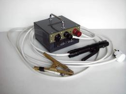
Transformer welding machine is simple and reliable. To make it yourself is within the power of everyone. To make a welding machine, we need an old transformer.

If there is no old transformer, then you can buy transformer iron for the core of the transformer. From practical experience it is known that the optimal core area is 40-55cm2.

In this case, the windings of the device will not warm up, and it will work reliably.
The transformer primary winding is wound with a special heat-resistant copper wire. The insulation of the wire should be fiberglass or cotton. It is not recommended to use wires with rubber or PVC insulation.
The power on the secondary winding, depending on the diameter of the electrode, is 3.5-4 kW, taking into account losses, the power on the primary winding will be 5-5.5 kW. In this case, the current on the primary winding can reach 25A. Therefore, the primary winding of the transformer must be wound with a wire of 5-6 mm2 or larger, which will increase the reliability of the transformer.
The number of turns of the primary winding is equal to: W1 \u003d (k2 * S) / U1where S- core cross-sectional area in cm2; k2 is a constant coefficient.
For the primary winding, the number of turns will be approximately 240. To be able to adjust the welding current, several taps are made in increments of 20-25 turns.
The secondary winding is wound with a copper wire with a cross section of 30-35 mm2. The number of turns is 65-70. On the secondary winding, bends are also made to adjust the current. The choice of insulation of the secondary wire should be given special attention. It must be heat resistant and reliable. It should be noted that the secondary winding is wound on both sides of the core in two different ways.

It should be remembered that winding should be done in one direction. Each layer of the winding must be insulated with a layer of additional cotton insulation.
Home-made inverter welding machine
A homemade inverter can be assembled from old radio components from a TV. But for this you need some skill and good knowledge of electronics. The circuit of a homemade inverter is implemented on cheap and affordable components.

The inverter operates on direct current with smooth regulation from 40 to 130 amperes. The maximum current of the primary winding of the transformer is 20A. for reliable operation, it is recommended to use an electrode no more than 3 mm. Welding voltage is activated by a button on the electrode holder. It is possible to cook on reverse polarity, which allows you to connect thin-sheet parts.
The diode bridge VD1-VD4 rectifies the mains voltage, the control lamp HL1 lights up and the capacitor C5 is charged. Welding can be started when the indicator light goes out.
The magnetic circuit of the T1 transformer used in the circuit is composed of three magnetic circuits PK30x16 made of 3000MNS-1 ferrite. The primary and secondary windings are wound with PSD1.68x10.4 copper wire. To fix the windings, a bandage of copper wire with a diameter of 1 mm is applied to them on fiberglass insulation. Bandage width 1cm.

All circuit elements are placed on a printed circuit board. For better heat dissipation from trinistors and diodes, they are mounted on a heat sink bolted to the board. The board is made of fiberglass 1.5 mm thick.

To improve the cooling of the circuit, it is necessary to use an additional fan, which is installed directly on the housing in which the inverter is located.
It is much easier to work with a welding inverter than a transformer apparatus. The seam is obtained better. Using a welding inverter allows you to cook ferrous and non-ferrous metals, sheet blanks. I think an experienced welder will not need welding lessonsto master this unit.


